RPM841-H11
Photo Link Module
3/9
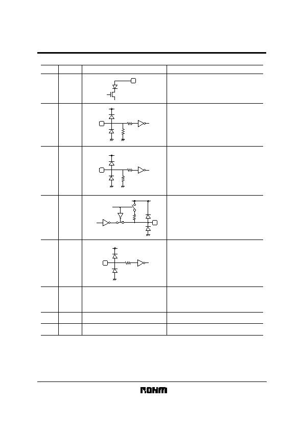
Terminal description
Terminal
Circuit
Function
Pin No
Ground Termianl
Power Supply Terminal
For preventing from infection, connect
a capacitor between VCC (6pin) and
GND (7pin).
Connect to Ground.
RC Transmitting Data Input Terminal
H : LED Emitting (Remote Control Mode)
CMOS Logic Level Input
Holding TX-RC='H' status, LED will be
turn off approximately 48祍.
Power-down Control Terminal
CMOS Logic Level Input
When input is 'H', it will stop the receiving
circuit and Pin-PD current.
H : POWERDOWN
L : OPERATION
Receiving Data Output Terminal
CMOS Logic Level Output
When PWDOWN (5pin)= 'H', the RXD
output will be pulled up to VCC at
approximately 300k&.
Transmitting Data Input Terminal
TXD input at PWDOWN=L
H : LED Emitting
CMOS Logic Level Input
Holding TXD="H" status, LED will be
turn off approximately 48祍.
LED ANODE Terminal
Other power source can be used
difference between LEDVCC and VCC.
1
2
3
4
LEDA
LED
1
TX-RC
VCC
240k
TXD
VCC
240k
RXD
5
6
7
VCC
300k
PWDOWN
PWDOWN
VCC
VCC
GND
Shield Case
发布紧急采购,3分钟左右您将得到回复。
相关PDF资料
RPM841-H16E4A1
MODULE IRDA 115.2KBPS 7-SMD
RPM870-H14E2
MODULE IRDA 115.2KBPS 8SMD
RPM871-E2
MODULE IRDA 115.2KBPS 8SMD
RPM871-H12E4
MODULE IRDA 115.2KBPS 8SMD
RPM871-H14E2
MODULE IRDA 115.2KBPS 8SMD
RPM872-E2
MODULE IRDA 115.2KBPS 8SMD
RPM872-H12E4
MODULE IRDA 115.2KBPS 8SMD
RPM872-H14E2
MODULE IRDA 115.2KBPS 8SMD
相关代理商/技术参数
RPM841-H11E2A2
制造商:ROHM Semiconductor 功能描述:IRDA TX/RX 0.1152MBPS 3V 8-PIN T/R - Tape and Reel 制造商:ROHM Semiconductor 功能描述:IRDA TX/RX 0.1152Mbps 3V
RPM841-H16
制造商:ROHM 制造商全称:Rohm 功能描述:IrDA Infrared Communication Module
RPM841-H16E4A
功能描述:光纤发射器、接收器、收发器 IRDA IR COMM TOP VIEW W/SHIELD RoHS:否 制造商:Omron Electronics 产品:Transmitters 数据速率:3.5 Gbps 波长:850 nm 最大工作温度: 最小工作温度: 封装 / 箱体: 封装:
RPM841-H16E4A1
功能描述:MODULE IRDA 115.2KBPS 7-SMD RoHS:是 类别:传感器,转换器 >> IrDA 收发器模块 系列:* 产品变化通告:Product Discontinuation 30/Sept/2009 产品目录绘图:GP2W Series 标准包装:1 系列:* 数据速率:115.2kbs(SIR) 电源电压:2.4 V ~ 3.6 V 无效电流,标准值@ 25° C:70µA 通信距离,低功率:20cm 方向:侧视图 工作温度:-40°C ~ 85°C 尺寸:8.3mm x 2.1mm x 1.7mm 标准:IrPHY 1.4 关机:* 包装:Digi-Reel® 其它名称:425-2614-6
RPM841-H16E4A2
功能描述:MODULE IRDA 115.2KBPS 7-SMD RoHS:是 类别:传感器,转换器 >> IrDA 收发器模块 系列:* 产品变化通告:Product Discontinuation 30/Sept/2009 产品目录绘图:GP2W Series 标准包装:1 系列:* 数据速率:115.2kbs(SIR) 电源电压:2.4 V ~ 3.6 V 无效电流,标准值@ 25° C:70µA 通信距离,低功率:20cm 方向:侧视图 工作温度:-40°C ~ 85°C 尺寸:8.3mm x 2.1mm x 1.7mm 标准:IrPHY 1.4 关机:* 包装:Digi-Reel® 其它名称:425-2614-6
RPM841-H16E4A3
功能描述:MODULE IRDA 115.2KBPS 7-SMD RoHS:是 类别:传感器,转换器 >> IrDA 收发器模块 系列:* 产品变化通告:Product Discontinuation 30/Sept/2009 产品目录绘图:GP2W Series 标准包装:1 系列:* 数据速率:115.2kbs(SIR) 电源电压:2.4 V ~ 3.6 V 无效电流,标准值@ 25° C:70µA 通信距离,低功率:20cm 方向:侧视图 工作温度:-40°C ~ 85°C 尺寸:8.3mm x 2.1mm x 1.7mm 标准:IrPHY 1.4 关机:* 包装:Digi-Reel® 其它名称:425-2614-6
RPM851
制造商:ROHM 制造商全称:Rohm 功能描述:IrDA wireless communication transceiver IC (supports Ver.1.0)
RPM851A
制造商:ROHM 制造商全称:Rohm 功能描述:IrDA wireless communication transceiver IC (supports Ver.1.0)
